CM6327A
USB Single-Chip Audio Solution for Mono Microphone
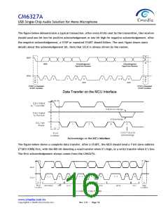
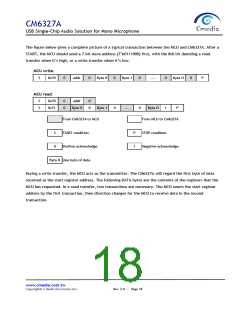
The figure below gives a complete picture of a typical transaction between the MCU and CM6327A. After a
START, the MCU should send a 7-bit slave address (7’b0111000) first, with the 8th bit denoting a read
transfer when it’s high, or a write transfer when it’s low.
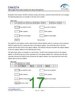
MCU write:
S
0x70
0
addr
0
Byte 0
0
Byte 1
0
…..
0
Byte N
0
P
MCU read:
S
S
0x70
0
0
addr
0
0
0x71
Byte 0
Byte 1
0
…..
0
Byte N
1
P
From CM6327A to MCU
START condition
From MCU to CM6327A
STOP condition
S
0
P
1
Positive acknowledge
Negative acknowledge
Byte N One byte of data
During a write transfer, the MCU acts as the transmitter. The CM6327A will regard the first byte of data
received as the start register address. The following DATA bytes are the contents of the registers that the
MCU has requested. In a read transfer, two transactions are necessary. The MCU resets the start register
address by the first transaction, then direction changes for the MCU to receive data in the second
transaction.
www.cmedia.com.tw
Copyright© C-Media Electronics Inc.
Rev. 2.0 ︱ Page 18

 CMEDIA [ C-MEDIA ELECTRONICS ]