Document Reference No.: FT_000247
V2-EVAL Vinculum II Evaluation Board Datasheet Version 2.0
Clearance No.: FTDI#148
Table of Contents
1 Introduction.................................................................... 3
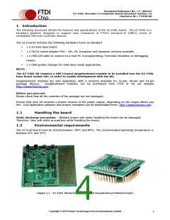
1.1 Handling the board ................................................................... 3
1.2 Environmental requirements..................................................... 3
1.3 Part Numbers............................................................................ 4
1.4 References................................................................................ 4
1.5 Acronyms and Abbreviations..................................................... 5
2 Board Description............................................................ 6
2.1 V2-EVAL Board Features ........................................................... 6
2.2 Specifications............................................................................ 6
3 V2-Eval Board Components and Interfaces ..................... 7
3.1 Block Diagram........................................................................... 8
3.1.1
3.1.2
Components. ............................................................................................ 9
Interfaces............................................................................................... 10
4 Initial Board Set-up & Test............................................ 11
4.1 Installing VNC2 Daughterboard .............................................. 11
4.2 Testing the board.................................................................... 12
5 Detailed Description of Board Components. .................. 13
5.1 Power Select Jumper JP6........................................................ 13
5.2 GPIO BUS Connectors ............................................................. 14
5.2.1
5.2.2
5.2.3
5.2.4
5.2.5
5.2.6
GPIO [0:7] Connector CN3 ....................................................................... 14
GPIO [8:15] Connector CN4...................................................................... 15
GPIO [16:23] Connector CN5.................................................................... 16
GPIO [24:31] Connector CN6.................................................................... 17
GPIO [32:39] Connector CN7.................................................................... 18
GPIO [40:43] Connector CN8.................................................................... 19
5.3 SPI Connector C9.................................................................... 20
5.4 UART Interface Connector C10................................................ 21
5.5 FIFO Interface Connector CN11 .............................................. 22
5.6 Prototyping area..................................................................... 23
5.7 USB1 interface CN1................................................................. 26
5.8 USB2 interface CN2................................................................. 27
5.9 VNC1L Interface Mode Select / GPIO Jumpers JP1, JP2.......... 28
5.10 User LEDs. LED3 – LED6.......................................................... 29
Copyright © 2010 Future Technology Devices International Limited
1

 FTDI [ FUTURE TECHNOLOGY DEVICES INTERNATIONAL LTD. ]