LT3840
applicaTions inForMaTion
MOSFET Selection
Note that RDS has a large positive temperature depen-
ON
dence. The MOSFET manufacturer’s data sheet contains
Two external N-channel MOSFETs are used with the
LT3840 controller, one top (main) switch, and one bot-
tom (synchronous) switch. The gate drive levels are set
a curve, RDS vs Temperature. In the main MOSFET,
ON
2
transition losses are proportional to V and can be con-
IN
siderably large in high voltage applications (V > 20V).
IN
by the INTV voltage. Therefore, standard or logic level
CC
Calculate the maximum transition losses:
threshold MOSFETs can be used.
QGSW
Selection criteria for the power MOSFETs include break-
P
= V •IOUT •fSW •
TRAN(TOP) IN
I
DRIVE
down voltage (BV ), maximum current (I
), on-
DSS
OUTMAX
resistance (RDS ) and gate charge.
ON
where Q
can be found in the MOSFET specification
GSW
First select a MOSFET with a BV
greater than V . Next
or calculated by:
DSS
IN
consider the package and current rating of the device. The
maximumcurrentratingofthedevicetypicallycorresponds
to a particular package. The RMS current of each device
is calculated below:
+ QGS
QGSW = QGD
2
and I
= 1A
DRIVE
ThetotalmaximumpowerdissipationsoftheMOSFETare:
VOUT
TopSwitchDuty Cycle(DCTOP)=
V
P
P
= P
+ P
COND(TOP) TRAN(TOP)
IN
TOP(TOTAL)
BOT(TOTAL)
= P
COND(BOT)
TopSwitchRMSCurrent =DCTOP •IOUTMAX
Complete a thermal analysis to ensure that the MOSFET’s
junction temperatures are not exceeded.
V – V
IN
OUT
BottomSwitchDuty Cycle(DCBOT )=
V
IN
T = T + P
• θ
JA
J
A
(TOTAL)
BottomSwitchRMSCurrent =DCBOT •IOUTMAX
where θ is the package thermal resistance and T is the
JA
A
ambient temperature. Keep the calculated T below the
J
Selectadevicethathasacontinuouscurrentratinggreater
than the calculated RMS current.
maximumspecifiedjunctiontemperature,typically150°C.
Note that when V is high and f is high, the transition
IN
SW
Lastly,considertheRDS andgatechargeoftheMOSFET.
losses may dominate. A MOSFET with higher RDS and
ON
ON
These two parameters are considered together because
lowergatechargemayprovidehigherefficiency.MOSFETs
theyaretypicallyinverselyproportionaltooneanother.The
with a higher voltage BV
specification usually have
DSS
RDS determines the conduction losses of the MOSFET
higher RDS and lower gate charge.
ON
ON
and the gate charge determines the switching losses.
A Schottky diode can be inserted in parallel with the
synchronous MOSFET to conduct during the dead time
between the conduction of the two power MOSFETs. This
preventsthebodydiodeofthebottomMOSFETfromturn-
ing on, storing charge during the dead time and requiring
a reverse recovery period.
The switching and conduction losses of each MOSFET
can be calculated as follows:
V
VIN
VIN – V
P
=IOUT(MAX)
•
•
OUT •RDS(ON)
2
COND(TOP)
COND(BOT)
P
=IOUT(MAX)
OUT •RDS(ON)
2
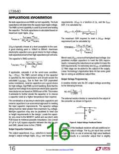
Input Capacitor Selection
VIN
Alocalinputbypasscapacitorisrequiredforbuckconvert-
ersbecausetheinputcurrentispulsedwithfastriseandfall
times. The input capacitor selection criteria are based on
3840fa
For more information www.linear.com/LT3840
15

 Linear [ Linear ]