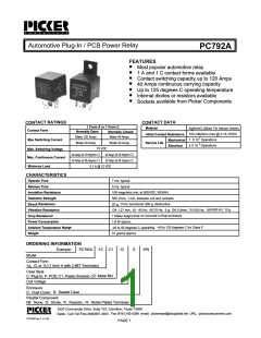
PC792A
PC792A
VES
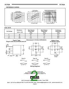
REFERENCE CUR
85o C
s
Maximum Switching Capacity at
Arc Extinguished Resistive Load
Coil Temp Rise
Ambient Temp 20 o C
Coil Temp Rise
Contacts Carrying 40A
100
90
80
70
60
50
40
100
50
100
95
90
85
80
75
70
65
60
55
50
N.O. Contact
N.C. Contact
40A
AT 20 oC
30
20
35A
30A
AT 85o C
10
5
20A
AT 125o
C
3
2
11 12 13 14 15 16 17 18
Coil Applied Voltage
1
50
100
11 12 13 14 15 16 17 18
Coil Applied Voltage
1
2
3
5
10 2030
Switching Voltage(VDC)
COIL DATA
Resistance
Must Operate
Voltage Max.
Must Release
Voltage Min.
Continuous
Voltage Max.
Coil Voltage
_
ohms + 10%
(VDC)
(VDC)
(VDC)
22
90
6
3.6
7.2
0.6
1.2
2.4
10.1
20.5
39.1
12
24
330
14.3
hes (millimeters)
Dimensions in Inc
Plug-In Type
Bottom View
nd PCB Case (P)
Plug-In Case (C) a
PC Board Layout
.665
.665
(16.9)
(16.9)
.031
(0.8)
87
87
.315
(8.0)
.705
(17.9)
.315
(8.0)
.705
(17.9)
.331
(8.4)
.331
(8.4)
1.04
(26.5)
87A
85
87A
30
86
86
85
.250
(6.3)
30
1.04
(26.5)
.453
(11.5)
.965
(24.5)
.047 X .094
(1.2 X 2.4)
All Holes
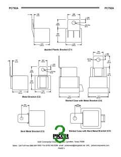
Form 1A
Form 1U
Form 1C
87a
87
87a
87
30
85
30
85
30
85
87
86
86
86
(+)
(-)
(+)
(-)
(+)
(-)
Wiring Diagrams
Notes:
Tolerances + .010 unless otherwise noted
rs to inrush of a lamp load
Maximum make current refe
ce maximum coil voltage to 72%
In 85 degree C ambient redu
exas 75006
e, Suite 102, Carrollton, T
3220 Commander Driv
pickercomponents.com
st@sbcglobal.net URL:
342-5296 email: pickerwe
PAGE 2
888) 997-3933 Fax (818)
Sales: Call Toll Free (

 PICKER [ PICKER COMPONENTS ]