PIN CONFIGURATION
ABSOLUTE MAXIMUM RATINGS(1)
Power Supply, V+ (referenced to IO pin) .......................................... 40V
Input Voltage, VI+N, VI–N (referenced to IO pin) ............................ 0V to V+
Storage Temperature Range ........................................ –55°C to +125°C
Lead Temperature (soldering, 10s) .............................................. +300°C
Output Current Limit ............................................................... Continuous
Junction Temperature ................................................................... +165°C
Top View
DIP and SOIC
1
2
3
4
5
6
7
IR1
VI–N
RG
RG
NC
IRET
IO
14 IR2
13 VI+N
12 VLIN
11 VREG
10 V+
NOTE: (1) Stresses above these ratings may cause permanent damage.
ELECTROSTATIC
DISCHARGE SENSITIVITY
9
8
B (Base)
E (Emitter)
This integrated circuit can be damaged by ESD. Burr-Brown
recommends that all integrated circuits be handled with
appropriate precautions. Failure to observe proper handling
and installation procedures can cause damage.
NC = No Internal Connection.
ESD damage can range from subtle performance degradation
to complete device failure. Precision integrated circuits may
be more susceptible to damage because very small parametric
changes could cause the device not to meet its published
specifications.
PACKAGE/ORDERING INFORMATION
PACKAGE
DRAWING TEMPERATURE
PRODUCT
PACKAGE
NUMBER(1)
RANGE
XTR105PA
XTR105P
XTR105UA
XTR105U
14-Pin Plastic DIP
14-Pin Plastic DIP
SO-14 Surface Mount
SO-14 Surface Mount
010
010
235
235
–40°C to +85°C
–40°C to +85°C
–40°C to +85°C
–40°C to +85°C
NOTE: (1) For detailed drawing and dimension table, please see end of data
sheet, or Appendix C of Burr-Brown IC Data Book.
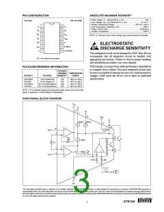
FUNCTIONAL BLOCK DIAGRAM
VLIN
IR1
12
1
IR2
14
VREG
V+
800µA
800µA
11
10
13
VI+N
5.1V
4
B
9
RLIN
1kΩ
Q1
100µA
RG
3
2
E
8
VIN
I = 100µA +
RG
VI–N
975Ω
25Ω
7
40
RG
IO = 4mA + VIN
•
(
)
6
IRET
The information provided herein is believed to be reliable; however, BURR-BROWN assumes no responsibility for inaccuracies or omissions. BURR-BROWN assumes no
responsibility for the use of this information, and all use of such information shall be entirely at the user’s own risk. Prices and specifications are subject to change without notice.
No patent rights or licenses to any of the circuits described herein are implied or granted to any third party. BURR-BROWN does not authorize or warrant any BURR-BROWN product
for use in life support devices and/or systems.
®
XTR105
3

 BB [ BURR-BROWN CORPORATION ]