3.0 Registers
CN8223
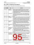
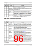
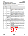
3.3 Configuration Control Registers
ATM Transmitter/Receiver with UTOPIA Interface
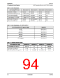
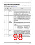
Table 3-4. Alarm Transmission
Line Framing/PHY Format
Alarm Control 7
Alarm Control 6
Alarm Control 5
Alarm Control 4
53-Octet DS1, E1 Modes
Not Used
Not Used
Not Used
Not Used
Idle Code
Not Used
MA FERF
Idle code
Not Used
Not Used
AIS
57-Octet External (PHY types 0–3)
57-octet Internal DS3 Mode
57-octet Internal G.751 E3 Mode
E3/E4 G.832 (PHY types 4–5)
53-octet Internal DS3 mode
G1 Yellow (PLCP)
G1 Yellow (PLCP)
G1 Yellow (PLCP)
Not Used
Not Used
X-Bit Yellow
A-Bit Yellow
MA Timing Marker
X-Bit Yellow
AIS
AIS
Not Used
AIS
Table 3-5. Alarm Transmission—STS–1/STS–3c/STM–1
STS-1/STS-3c/STM-1 (PHY Types 6-7) Alarm
Control Bit
Line AIS
Line FERF
Alarm Control 4
Alarm Control 5
Alarm Control 6
Alarm Control 7
Alarm Control 8
Alarm Control 9
Path Yellow
Path FERF
Path AIS
SPE Unequipped
Table 3-6. Overhead Generation Disable
Line Framing/PHY Format
Overhead Bit 3
Overhead Bit 2
Overhead Bit 1
Overhead Bit 0
57-Octet Modes (PHY types 0–3)
E3/E4 G.832 (PHY types 4–5)
A1, A2, Pn
A1, A2
B1
EM
C1
MA
Trailer Bits
Not Used
C1, C2
STS-1/STS-3c/STM-1 (PHY types 6–7)
A1, A2
B1, B2, B3
H1, H2, H3, H4
3-8
Conexant
100046C

 CONEXANT [ CONEXANT SYSTEMS, INC ]