External Clock Operation
3.4.3
External Clock Source
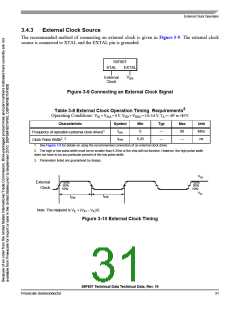
The recommended method of connecting an external clock is given in Figure 3-9. The external clock
source is connected to XTAL and the EXTAL pin is grounded.
56F807
XTAL
EXTAL
V
External
Clock
SS
Figure 3-9 Connecting an External Clock Signal
5
Table 3-8 External Clock Operation Timing Requirements
Operating Conditions: VSS = VSSA = 0 V, VDD = VDDA = 3.0–3.6 V, TA = –40° to +85°C
Characteristic
Symbol
fosc
Min
0
Typ
—
Max
80
Unit
MHz
ns
Frequency of operation (external clock driver)1
Clock Pulse Width2, 3
tPW
6.25
—
—
1. See Figure 3-9 for details on using the recommended connection of an external clock driver.
2. The high or low pulse width must be no smaller than 6.25ns or the chip will not function. However, the high pulse width
does not have to be any particular percent of the low pulse width.
3. Parameters listed are guaranteed by design.
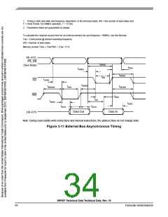
VIH
External
Clock
90%
50%
10%
90%
50%
10%
VIL
tPW
tPW
Note: The midpoint is VIL + (VIH – VIL)/2.
Figure 3-10 External Clock Timing
56F807 Technical Data Technical Data, Rev. 16
Freescale Semiconductor
31

 FREESCALE [ Freescale ]