71M6543F/H and 71M6543G/GH Data Sheet
The RMS values can be computed by the MPU from the squared current and voltage samples as follows:
VxSQSUM ⋅ LSBV ⋅3600⋅ FS
IxSQSUM ⋅ LSBI ⋅3600⋅ FS
VxRMS
=
IxRMS
=
NACC
NACC
Other transfer variables include those available for frequency and phase measurement, and those reflecting
the count of the zero-crossings of the mains voltage and the battery voltage. These transfer variables are
listed in Table 84.
MAINEDGE_X reflects the number of half-cycles accounted for in the last accumulated interval for the AC
signal of the phase specified in the FREQSEL[1 :0] field of the CECONFIG register (CE RAM 0x20[7:6]) .
MAINEDGE_X is useful for implementing a real-time clock based on the input AC signal.
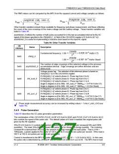
Table 84: Other Transfer Variables
CE
Name
Description
Address
2184Hz
232
≡
≡
≈ 0.509⋅10−6
≈ 0.587⋅10−6
Fundamental frequency: LSB
LSB
Hz(for CT)
FREQ_X
0x82
2520Hz
Hz(for Shunt)
232
The number of edge crossings of the selected voltage in the previous
MAINEDGE_X accumulation interval. Edge crossings are either direction and are
0x83
0x94
debounced.
Voltage phase lag. The selection of the reference phase is based on
FREQSEL[1:0] in the CECONFIG register:
If FREQSEL[1:0] selects phase A: Phase lag from A to B.
If FREQSEL[1:0] selects phase B: Phase lag from B to C.
If FREQSEL[1:0] selects phase C: Phase lag from C to A.
Angle in degrees is (0 to 360): PH_AtoB_X * 360/NACC + 2.4*15/13 (for CT)
Angle in degrees is (0 to 360): PH_AtoB_X * 360/NACC + 2.4 (for Shunt)
If FREQSEL[1:0] selects phase A: Phase lag from A to C.
PH_AtoB_X
PH_AtoC_X
If FREQSEL[1:0] selects phase B: Phase lag from B to A.
If FREQSEL[1:0] selects phase C: Phase lag from C to B.
0x95
Angle in degrees is (0 to 360): PH_AtoC_X * 360/NACC + 4.8*15/13 (for CT)
Angle in degrees is (0 to 360): PH_AtoC_X * 360/NACC + 4.8*15/13 (for Shunt)
Phase angle measurement accuracy can be increased by writing values > 1 into V_ANG_CNT (see
Table 79).
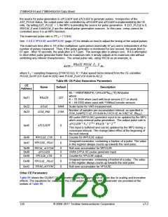
5.4.9 Pulse Generation
Table 85 describes the CE pulse generation parameters.
The combination of the CECONFIG PULSE_SLOW (CE RAM 0x20[0]) and PULSE_FAST (CE RAM 0x20[1])
bits controls the speed of the pulse rate. The default values of 0 and 0 maintain the original pulse rate
given by the Kh equation.
WRATE (CE RAM 0x21) controls the number of pulses that are generated per measured Wh and VARh
quantities. The lower WRATE is the slower the pulse rate for measured energy quantity. The metering
constant Kh is derived from WRATE as the amount of energy measured for each pulse. That is, if Kh =
1Wh/pulse, a power applied to the meter of 120 V and 30 A results in one pulse per second. If the load is
240 V at 150 A, ten pulses per second are generated.
Control is transferred to the MPU for pulse generation if EXT_PULSE = 1 (CE RAM 0x20[5]). In this case,
the pulse rate is determined by APULSEW and APULSER (CE RAM 0x45 and 0x49). The MPU has to load
v1.2
© 2008–2011 Teridian Semiconductor Corporation
127

 MAXIM [ MAXIM INTEGRATED PRODUCTS ]