5 V/1 2 V/1 5 V o r Ad ju s t a b le , High-Effic ie nc y,
Low I , Ste p-Up DC-DC Controlle rs
Q
0–MAX73
LBO V15
V12
V5
FB
V+
DUAL-MODE
MAX773 ONLY
COMPARATOR
MAX770–MAX773
LBI
N
N
SHDN
200mV
BIAS
CIRCUITRY
1.5V
REFERENCE
REF
ERROR
COMPARATOR
ONE-SHOT
MAX770
MAX771
MAX772
Q
TRIG
V+
N
6V
SGND
EXTH
F/F
S
Q
EXT
CONTROL
R
LOW-VOLTAGE
OSCILLATOR
2.5V
MAX773
ONLY
ONE-SHOT
TRIG
EXTL
Q
CURRENT-SENSE
AMPLIFIER
0.2V
0.1V
EXT
MAX770
MAX771
MAX772
CS
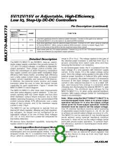
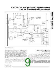
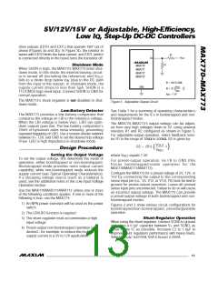
Figure 1. Block Diagram
Floating the shunt-regulator ground (SGND) disables
the shunt regulator. To enable it, connect SGND to
GND. The shunt regulator requires 1mA minimum cur-
rent for proper operation; the maximum current must
not exceed 20mA. The MAX773 operates in non-boot-
strapped mode when the shunt regulator is used, and
EXT swings between the 6V shunt-regulator voltage
and GND.
Ex t e rn a l P o w e r-Tra n s is t o r
Co n t ro l Circ u it ry
PFM Control Scheme
The MAX770–MAX773 use a proprietary current-limited
PFM control scheme to provide high efficiency over a
wide range of load currents. This control scheme com-
bines the ultra-low supply current of PFM converters (or
pulse skippers) with the high full-load efficiency of
PWM converters.
When using the shunt regulator, use an N-channel pow-
er FET instead of an NPN power transistor as the power
switch. Otherwise, excessive base drive will collapse
the shunt regulator.
Unlike tra d itiona l PFM c onve rte rs , the MAX770–
MAX773 use a sense resistor to control the peak induc-
tor c urre nt. The y a ls o op e ra te with hig h s witc hing
_______________________________________________________________________________________
9

 MAXIM [ MAXIM INTEGRATED PRODUCTS ]