Freescale Semiconductor, Inc.
MSCAN Controller
The above behaviour cannot be achieved with a single transmit buffer.
That buffer must be reloaded right after the previous message has been
sent. This loading process lasts a definite amount of time and has to be
completed within the inter-frame sequence (IFS) in order to be able to
send an uninterrupted stream of messages. Even if this is feasible for
limited CAN bus speeds it requires that the CPU reacts with short
latencies to the transmit interrupt.
A double buffer scheme would de-couple the re-loading of the transmit
buffers from the actual message sending and as such reduces the
reactiveness requirements on the CPU. Problems may arise if the
sending of a message would be finished just while the CPU re-loads the
second buffer, no buffer would then be ready for transmission and the
bus would be released.
At least three transmit buffers are required to meet the first of above
requirements under all circumstances. The msCAN12 has three transmit
buffers.
The second requirement calls for some sort of internal prioritisation
which the msCAN12 implements with the local priority concept
described below.
17.4.2 Receive Structures
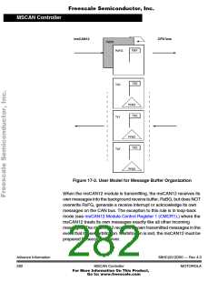
The received messages are stored in a two stage input FIFO. The two
message buffers are alternately mapped into a single memory area (see
Figure 17-2). While the background receive buffer (RxBG) is exclusively
associated to the msCAN12, the foreground receive buffer (RxFG) is
addressable by the CPU12. This scheme simplifies the handler software
as only one address area is applicable for the receive process.
Both buffers have a size of 13 bytes to store the CAN control bits, the
identifier (standard or extended) and the data contents (for details see
Programmer’s Model of Message Storage).
The receiver full flag (RXF) in the msCAN12 receiver flag register
(CRFLG) (see msCAN12 Receiver Flag Register (CRFLG)) signals the
status of the foreground receive buffer. When the buffer contains a
correctly received message with matching identifier this flag is set.
Advance Information
280
68HC(9)12D60 — Rev 4.0
MSCAN Controller
MOTOROLA
For More Information On This Product,
Go to: www.freescale.com

 MOTOROLA [ MOTOROLA ]