SN54AS867, SN54AS869
SN74ALS867A, SN74ALS869, SN74AS867, SN74AS869
SYNCHRONOUS 8-BIT UP/DOWN COUNTERS
SDAS115C – DECEMBER 1982 – REVISED JANUARY 1995
†
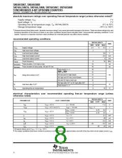
absolute maximum ratings over operating free-air temperature range (unless otherwise noted)
Supply voltage, V
. . . . . . . . . . . . . . . . . . . . . . . . . . . . . . . . . . . . . . . . . . . . . . . . . . . . . . . . . . . . . . . . . . . . . . . . 7 V
CC
Input voltage, V . . . . . . . . . . . . . . . . . . . . . . . . . . . . . . . . . . . . . . . . . . . . . . . . . . . . . . . . . . . . . . . . . . . . . . . . . . . . 7 V
I
Operating free-air temperature range, T : SN74ALS867A . . . . . . . . . . . . . . . . . . . . . . . . . . . . . . . . 0°C to 70°C
A
Storage temperature range . . . . . . . . . . . . . . . . . . . . . . . . . . . . . . . . . . . . . . . . . . . . . . . . . . . . . . . –65°C to 150°C
†
Stresses beyond those listed under “absolute maximum ratings” may cause permanent damage to the device. These are stress ratings only, and
functional operation of the device at these or any other conditions beyond those indicated under “recommended operating conditions” is not
implied. Exposure to absolute-maximum-rated conditions for extended periods may affect device reliability.
recommended operating conditions
SN74ALS867A
MIN NOM MAX
UNIT
V
V
V
Supply voltage
4.5
2
5
5.5
V
V
CC
High-level input voltage
Low-level input voltage
IH
0.8
–0.4
8
V
IL
I
I
f
t
t
High-level output current
Low-level output current
Clock frequency
mA
mA
MHz
ns
OH
OL
0
14
10
10
15
12
12
12
3
35
clock
w(clock)
w(clear)
Pulse duration, CLK high or low
Pulse duration of clear pulse, S0 and S1 low
ns
Data inputs A–H
ENP or ENT
t
su
S0 low and S1 high (load)
S0 high and S1 low (count down)
S0 and S1 high (count up)
S0 high after S1↑ or S1 high after S0↑
Data inputs A–H
ns
Setup time before CLK↑
t
h
ns
Hold time after CLK↑
0
T
A
Operating free-air temperature
0
70
°C
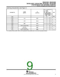
electrical characteristics over recommended operating free-air temperature range (unless
otherwise noted)
SN74ALS867A
PARAMETER
TEST CONDITIONS
UNIT
‡
MIN TYP
MAX
V
V
V
V
= 4.5 V,
I = –18 mA
–1.2
V
V
IK
CC
I
= 4.5 V to 5.5 V,
I
I
I
= –0.4 mA
= 4 mA
V
CC
–2
OH
CC
OH
OL
OL
0.25
0.35
0.4
0.5
V
OL
V
CC
= 4.5 V
V
= 8 mA
I
I
I
I
I
V
CC
V
CC
V
CC
V
CC
V
CC
= 5.5 V,
= 5.5 V,
= 5.5 V,
= 5.5 V,
= 5.5 V
V = 7 V
0.1
mA
µA
I
I
V = 2.7 V
I
20
IH
IL
V = 0.4 V
I
–0.2
–112
45
mA
mA
mA
§
V
O
= 2.25 V
–30
O
28
CC
‡
§
All typical values are at V
= 5 V, T = 25°C.
A
CC
The output conditions have been chosen to produce a current that closely approximates one half of the true short-circuit output current, I
.
OS
8
POST OFFICE BOX 655303 • DALLAS, TEXAS 75265

 TI [ TEXAS INSTRUMENTS ]