eorex
EP1117
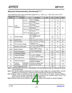
Electrical Characteristics (Continued) (Note 3)
Unless otherwise noted, these specifications apply over CIN = 10μF, COUT = 10μF, and TA=0°C to 70°C.
Typical values refer to TA=25°C.
Symbol
Parameter
Conditions
(VIN -VOUT)=3V,
Min.
Typ.
0.1
Max.
0.4
Units
%
EP1117
(Note4)
(Note4)
(Note4)
(Note4)
0≤IOUT≤1A
VIN=3.25V,
EP1117-18
EP1117-25
EP1117-33
EP1117-50
1
1
1
1
10
10
10
15
0≤IOUT≤1A
VIN=3.95V,
0≤IOUT≤1A
Load
REGLOAD
Regulation
mV
VIN=4.75V,
0≤IOUT≤1A
VIN=6.5V,
0≤IOUT≤1A
(Note4)
IOUT=100mA
1
1.1
1.2
1.3
(Note5)
I
I
OUT=500mA
OUT=1A
VD
Dropout Voltage
1.05
1.1
V
ILIMIT
IFB
Current Limit
(VIN -VOUT)=5V, TJ=25°C
1.1
60
A
FB Pin Current
(VIN -VOUT)=3V, IOUT=10mA
60
0.2
5
120
5
μA
10mA≤IOUT≤1A,
1.4V≤(VIN -VOUT)≤10.75V
∆IFB
IO
FB Pin Current Change
Minimum Load Current
Ripple Rejection
μA
mA
dB
(Note6)
(VIN -VOUT)=10.75V
10
fRIPPLE=120Hz, VRIPPLE
=
PSRR
75
1VP-P, (VIN -VOUT)=3V
TJ=25°C, 30ms Pulse
TR
TS
LS
Thermal Regulation
Temperature Stability
Long-Term Stability
0.01
0.5
0.02
%/W
%
TJ=125°C, 1000Hrs
0.3
%
TJ=25°C, 10Hz≤F≤10KHz,
VN
RMS Output Noise
Thermal Resistance
0.003
15
%
(% of VOUT
)
Junction to case, at Tab
junction to ambient
θth
°C/W
SOT-223
TO-252
117
92
Thermal
Junction-to-Ambient (No
heat sink ;No air flow)
θJA
°C/W
°C
Resistance
OT
Over Temperature Point
150
Note 3: 100% production test at +25°C. Specifications over the temperature range are guaranteed by design
and characterization.
Note 4: See thermal regulation specifications for changes in output voltage due to heating effects. Load line
regulations are measured at a constant junction temperature by low duty cycle pulse testing.
Note 5:Dropout voltage is specified over the full output current range of the device. Dropout voltage is
defined as the minimum input/output differential measured at the specified output current. Test
points and limits are also shown on the Dropout Voltage Curve.
Note 6: Minimum load current is defined as the minimum output current required to maintain regulation.
Jul. 2006
www.eorex.com
4/10

 EOREX [ EOREX CORPORATION ]