eorex
EP1117
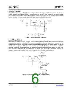
Output Voltage
The EP1117 develops a 1.25V reference voltage between the output and the FB terminal. By placing a
resistor between these two terminals, a constant current is caused to flow through R1 and down through
R2 to set the overall output voltage. Normally this current is chosen to be the specified minimum load
current of 10mA. For fixed voltage devices R1 and R2 are included in the device.
R2
⎛
⎝
⎞
⎟
⎠
VOUT= VREF × 1 +
+I R2
FB
⎜
R1
Figure 1-Basic Adjustable Regulator
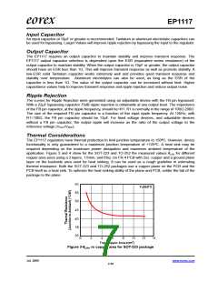
Load Regulation
When the adjustable regulator is used, load regulation will be limited by the resistance of the wire
connecting the regulator to the load. The datasheet specification for load regulation is measured at the
output pin of the EP1117. Best load regulation is obtained when the top of the resistor divider (R1) is tied
directly to the output pin of the device, not to the load. For fixed voltage devices, the top of R1 is
internally connected to the output, and the ground pin can be connected to low side of the load. If R1
were connected to the load, RP is multiplied by the divider ratio, the effective resistance between the
regulator and the load would be: RP×(1+R2/R1), where RP is Parasitic Line Resistance.
Rp
Parasitic
Line Resistance
VIN
VOUT
EP1117
FB
VIN
R1
Connect
RL
R1 to Case
R2
Connect
R2 to Load
Figure 2-Connections for Best Load Regulation
Jul. 2006
www.eorex.com
6/10

 EOREX [ EOREX CORPORATION ]