DDR SDRAM
Notes
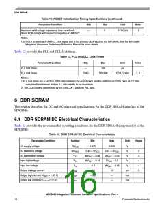
Table 13. DDR SDRAM DC Electrical Characteristics
Parameter/Condition
Symbol
Min
Max
Unit
MVREF input leakage current
IVREF
—
100
μA
Notes:
1.GVDD is expected to be within 50 mV of the DRAM GVDD at all times.
2.MVREF is expected to be equal to 0.5 × GVDD, and to track GVDD DC variations as measured at the receiver.
Peak-to-peak noise on MVREF may not exceed 2% of the DC value.
3.VTT is not applied directly to the device. It is the supply to which far end signal termination is made and is expected
to be equal to MVREF. This rail should track variations in the DC level of MVREF
.
4.VIH can tolerate an overshoot of 1.2V over GVDD for a pulse width of ≤3 ns, and the pulse width cannot be greater
than tMCK. VIL can tolerate an undershoot of 1.2V below GND for a pulse width of ≤3 ns, and the pulse width
cannot be greater than tMCK
.
5.Output leakage is measured with all outputs disabled, 0 V ≤ VOUT ≤ GVDD
.
Table 14 provides the DDR capacitance.
Table 14. DDR SDRAM Capacitance
Parameter/Condition
Symbol
Min
Max
Unit
Notes
Input/output capacitance: DQ, DQS, MSYNC_IN
Delta input/output capacitance: DQ, DQS
Note:
CIO
6
8
pF
pF
1
1
CDIO
—
0.5
1.This parameter is sampled. GVDD = 2.5 V 0.125 V, f = 1 MHz, TA = 25°C, VOUT = GVDD/2, VOUT (peak to peak) = 0.2 V.
6.2 DDR SDRAM AC Electrical Characteristics
This section provides the AC electrical characteristics for the DDR SDRAM interface.
6.2.1 DDR SDRAM Input AC Timing Specifications
Table 15 provides the input AC timing specifications for the DDR SDRAM interface.
Table 15. DDR SDRAM Input AC Timing Specifications
At recommended operating conditions with GVDD of 2.5 V 5%.
Parameter
AC input low voltage
Symbol
Min
Max
Unit
Notes
VIL
VIH
—
MVREF – 0.31
GVDD + 0.3
V
V
AC input high voltage
MVREF + 0.31
MDQS—MDQ/MECC input skew per byte
tDISKEW
ps
1, 2
-750
-1125
750
1125
For DDR = 333 MHz
For DDR ≤ 266 MHz
Note:
1.Maximum possible skew between a data strobe (MDQS[n]) and any corresponding bit of data (MDQ[8n + {0...7}] if
0 ≤ n ≤ 7) or ECC (MECC[{0...7}] if n=8).
2.For timing budget analysis, the MPC8540 consumes ±550 ps of the total budget.
MPC8540 Integrated Processor Hardware Specifications, Rev. 4
Freescale Semiconductor
17

 FREESCALE [ Freescale ]