High Current PN Half Bridge
BTN8982TA
Block Description and Characteristics
5.3
Protection Functions
The device provides integrated protection functions. These are designed to prevent IC destruction under fault
conditions described in the data sheet. Fault conditions are considered as “outside” normal operating range.
Protection functions are not to be used for continuous or repetitive operation, with the exception of the current
limitation (Chapter 5.3.3). In case of overtemperature the BTN8982TA will apply the slew rate determined by the
connected slew rate resistor. In current limitation mode the highest slew rate possible will be applied independent
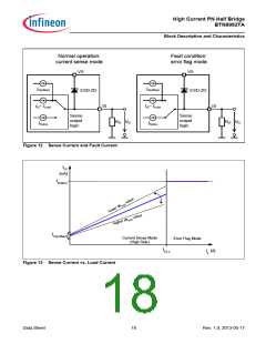
of the connected slew rate resistor. Overtemperature and overcurrent are indicated by a fault current IIS(LIM) at the
IS pin as described in the paragraph “Status Flag Diagnosis with Current Sense Capability” on Page 17 and
Figure 12.
5.3.1
Undervoltage Shut Down
To avoid uncontrolled motion of the driven motor at low voltages the device shuts off (output is tri-state), if the
supply voltage drops below the switch-off voltage VUV(OFF). The IC becomes active again with a hysteresis VUV(HY)
if the supply voltage rises above the switch-on voltage VUV(ON)
.
5.3.2
Overtemperature Protection
The BTN8982TA is protected against overtemperature by an integrated temperature sensor. Overtemperature
leads to a shut down of both output stages. This state is latched until the device is reset by a low signal with a
minimum length of treset at the INH pin, provided that its temperature has decreased at least the thermal hysteresis
ΔT in the meantime.
Repetitive use of the overtemperature protection impacts lifetime.
5.3.3
Current Limitation
The current in the bridge is measured in both switches. As soon as the current in forward direction in one switch
(high side or low side) is reaching the limit ICLx, this switch is deactivated and the other switch is activated for tCLS
During that time all changes at the IN pin are ignored. However, the INH pin can still be used to switch both
MOSFETs off. After tCLS the switches return to their initial setting. The error signal at the IS pin is reset after 2 * tCLS
.
.
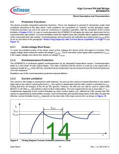
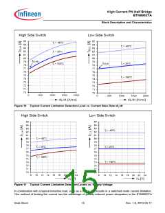
Unintentional triggering of the current limitation by short current spikes (e.g. inflicted by EMI coming from the
motor) is suppressed by internal filter circuitry. Due to thresholds and reaction delay times of the filter circuitry the
effective current limitation level ICLx depends on the slew rate of the load current dI/dt as shown in Figure 10.
IL
tCLS
ICLx
ICLx0
t
Figure 9
Timing Diagram Current Limitation (Inductive Load)
Data Sheet
14
Rev. 1.0, 2013-05-17

 INFINEON [ Infineon ]