LT3592
APPLICATIONS INFORMATION
Oscillator
The BRIGHT mode current is given by:
= 200mV/R
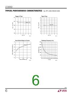
The frequency of operation is programmed by an external
I
BRIGHT
SENSE
resistor from R to ground. Table 1 shows R values for
T
T
The DIM mode current is 10% of the BRIGHT mode value.
The maximum allowed DC value of the BRIGHT mode cur-
rentis500mA.Whentherecommendedcomponentvalues
are used in a 900kHz 2 LED application, the transient from
switching between BRIGHT and DIM currents will be less
than 50μs in duration.
commonlyusedoscillatorfrequencies,andrefertotheTypi-
cal Performance Characteristics curve for other values.
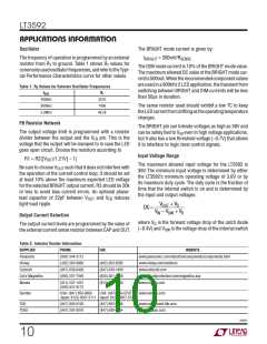
Table 1. RT Values for Selector Oscillator Frequencies
f
R
T
OSC
400kHz
900kHz
2.2MHz
357k
140k
48.7k
The sense resistor used should exhibit a low TC to keep
theLEDcurrentfromdriftingastheoperatingtemperature
changes.
FB Resistor Network
The BRIGHT pin can tolerate voltages as high as 36V and
The output voltage limit is programmed with a resistor
can be safely tied to V even in high voltage applications,
IN
divider between the output and the V pin. This is the
but it also has a low threshold voltage (~0.7V) that allows
FB
voltage that the output will be clamped to in case the LED
it to interface to logic level control signals.
goes open circuit. Choose the resistors according to
Input Voltage Range
R1 = R2([V /1.21V] – 1)
OUT
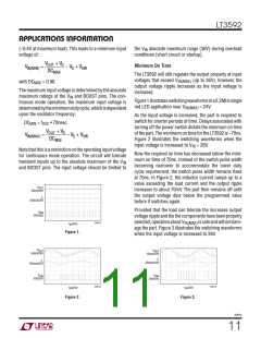
The maximum allowed input voltage for the LT3592 is
36V. The minimum input voltage is determined by either
the LT3592’s minimum operating voltage of 3.6V or by
its maximum duty cycle. The duty cycle is the fraction of
time that the internal switch is on and is determined by
the input and output voltages:
Be sure to choose V
such that it does not interfere with
OUT
the operation of the current control loop; it should be set
at least 10% above the maximum expected LED voltage
for the selected BRIGHT output current. R2 should be 20k
or less to avoid bias current errors. An optional phase-
lead capacitor of 22pF between V
light-load ripple.
and V reduces
OUT
FB
VOUT + VD
DC =
V – VSW + VD
IN
Output Current Selection
where V is the forward voltage drop of the catch diode
D
The output current levels are programmed by the value of
the external current sense resistor between CAP and OUT.
(~0.4V) and V is the voltage drop of the internal switch
SW
Table 2. Inductor Vendor Information
SUPPLIER
Panasonic
Vishay
PHONE
FAX
WEBSITE
www.panasonic.com/industrial/components/components.html
www.vishay.com/resistors
(800) 344-2112
(402) 563-6866
(847) 639-6400
(800) 227-7040
(402) 563-6296
(847) 639-1469
(650) 361-2508
(814) 238-0490
Coilcraft
www.coilcraft.com
CoEv Magnetics
Murata
www.circuitprotection.com/magnetics.asp
www.murata.com
(814) 237-1431
(800) 831-9172
Sumida
USA: (847) 956-0666
USA: (847) 956-0702
www.sumida.com
Japan: 81(3) 3607-5111 Japan: 81(3) 3607-5144
TDK
(847) 803-6100
(847) 297-0070
(847) 803-6296
(847) 699-7864
www.component.tdk.com
www.tokoam.com
TOKO
3592fc
10

 Linear Systems [ Linear Systems ]