TOP252-262
packages). Duty cycle is reduced from DCMAX through the
reduction of the on-time when IC is increased beyond IB. This
operation is identical to the PWM control of all other TOPSwitch
families. TOPSwitch-HX only operates in this mode if the cycle-
by-cycle peak drain current stays above kPS(UPPER)*ILIMIT(set),
where kPS(UPPER) is 55% (typical) and ILIMIT(set) is the current limit
externally set via the X or M pin.
fOSC
+
Switching
Frequency
fOSC
-
4 ms
Variable Frequency PWM mode: When peak drain current is
lowered to kPS(UPPER)* ILIMIT(set) as a result of power supply load
reduction, the PWM modulator initiates the transition to variable
frequency PWM mode, and gradually turns off frequency jitter.
VDRAIN
Time
In this mode, peak drain current is held constant at kPS(UPPER)
LIMIT(set) while switching frequency drops from the initial full
frequency of fOSC (132 kHz or 66 kHz) towards the minimum
*
I
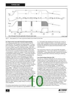
Figure 10. Switching Frequency Jitter (Idealized VDRAIN Waveforms).
frequency of fMCM(MIN) (30 kHz typical). Duty cycle reduction is
accomplished by extending the off-time.
(half frequency), which may be preferable in some cases such
as noise sensitive video applications or a high efficiency
standby mode. Otherwise, the FREQUENCY pin should be
connected to the SOURCE pin for the default 132 kHz. In the
M, P and G packages and the TOP259-261 Y package option,
the full frequency PWM mode is set at 66 kHz, for higher
efficiency and increased output power in all applications.
Low Frequency PWM mode: When switching frequency
reaches fMCM(MIN) (30 kHz typical), the PWM modulator starts to
transition to low frequency mode. In this mode, switching
frequency is held constant at fMCM(MIN) and duty cycle is reduced,
similar to the full frequency PWM mode, through the reduction
of the on-time. Peak drain current decreases from the initial
value of kPS(UPPER)* ILIMIT(set) towards the minimum value of
To further reduce the EMI level, the switching frequency in the
full frequency PWM mode is jittered (frequency modulated) by
approximately 2.5 kHz for 66 kHz operation or 5 kHz for
132 kHz operation at a 250 Hz (typical) rate as shown in
Figure 10. The jitter is turned off gradually as the system is
entering the variable frequency mode with a fixed peak drain
current.
k
PS(LOWER)*ILIMIT(set), where kPS(LOWER) is 25% (typical) and ILIMIT(set) is
the current limit externally set via the X or M pin.
Multi-Cycle-Modulation mode: When peak drain current is
lowered to kPS(LOWER)*ILIMIT(set), the modulator transitions to multi-
cycle-modulation mode. In this mode, at each turn-on, the
modulator enables output switching for a period of TMCM(MIN) at
the switching frequency of fMCM(MIN) (4 or 5 consecutive pulses at
30 kHz) with the peak drain current of kPS(LOWER)*ILIMIT(set), and
stays off until the CONTROL pin current falls below IC(OFF). This
mode of operation not only keeps peak drain current low but
also minimizes harmonic frequencies between 6 kHz and
30 kHz. By avoiding transformer resonant frequency this way,
all potential transformer audible noises are greatly supressed.
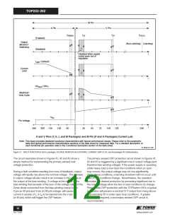
Pulse Width Modulator
The pulse width modulator implements multi-mode control by
driving the output MOSFET with a duty cycle inversely
proportional to the current into the CONTROL pin that is in
excess of the internal supply current of the chip (see Figure 9).
The feedback error signal, in the form of the excess current, is
filtered by an RC network with a typical corner frequency of
7 kHz to reduce the effect of switching noise in the chip supply
current generated by the MOSFET gate driver.
Maximum Duty Cycle
The maximum duty cycle, DCMAX, is set at a default maximum
value of 78% (typical). However, by connecting the VOLTAGE-
MONITOR or MULTI-FUNCTION pin (depending on the
package) to the rectified DC high voltage bus through a resistor
with appropriate value (4 MΩ typical), the maximum duty cycle
can be made to decrease from 78% to 40% (typical) when input
line voltage increases from 88 V to 380 V, with dual gain slopes.
To optimize power supply efficiency, four different control
modes are implemented. At maximum load, the modulator
operates in full frequency PWM mode; as load decreases, the
modulator automatically transitions, first to variable frequency
PWM mode, then to low frequency PWM mode. At light load,
the control operation switches from PWM control to multi-cycle-
modulation control, and the modulator operates in multi-cycle-
modulation mode. Although different modes operate differently
to make transitions between modes smooth, the simple
relationship between duty cycle and excess CONTROL pin
current shown in Figure 9 is maintained through all three PWM
modes. Please see the following sections for the details of the
operation of each mode and the transitions between modes.
Error Amplifier
The shunt regulator can also perform the function of an error
amplifier in primary side feedback applications. The shunt
regulator voltage is accurately derived from a temperature-
compensated bandgap reference. The CONTROL pin dynamic
impedance ZC sets the gain of the error amplifier. The
CONTROL pin clamps external circuit signals to the VC voltage
level. The CONTROL pin current in excess of the supply
current is separated by the shunt regulator and becomes the
feedback current Ifb for the pulse width modulator.
Full Frequency PWM mode: The PWM modulator enters full
frequency PWM mode when the CONTROL pin current (IC)
reaches IB. In this mode, the average switching frequency is
kept constant at fOSC (66 kHz for P, G and M packages and
TOP259-261 Y, pin selectable 132 kHz or 66 kHz for Y and E/L
9
www.powerint.com
Rev. F 01/09

 POWERINT [ Power Integrations ]