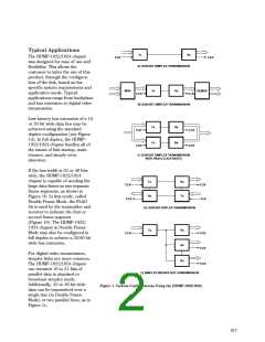
For timing diagrams for the
standard configurations, see the
Appendix section entitled Link
Configuration Examples.
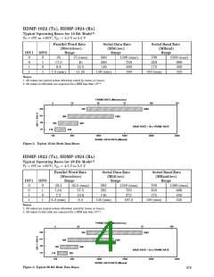
to the table entitled “Typical
Operating Rates for 20 Bit Mode”
on the next page, a setting of
DIV1/DIV0 = logic ‘0/0’ allows a
parallel input word rate of 29.2 to
62.5 MHz . This setting easily
accommodates the required 55
MHz word rate. The user serial
data rate can be calculated as:
gives a lower rate of 29.2 MHz.
These transition data rates are
stated in the tables as typical
values and may vary between
individual parts. Each transmitter/
receiver has continuous band
coverage across its entire 150 to
1500 MBaud range and has
overlap between ranges. Each
transmitter/receiver will permit a
35 MHz parallel data rate, but it is
suggested that DIV0 be a jumper
that can be set either to logic ‘1’
(open) or logic ‘0’ (ground). This
allows the design to accommodate
both ranges for maximum flexibil-
ity. This technique is recom-
The HDMP-1022/1024 chipset
can support serial transmission
rates from 150 MBd to 1.5 GBd
for each of these configurations.
The chipset requires the user to
input the link data rate by assert-
ing DIV1 and DIV0 accordingly.
To determine the DIV1/DIV0
setting necessary for each
Serial
20 bit
word sec
55 Mw
Data Rate = (––––––) (––––––)
= 1100 MBits/sec
The baud rate includes an
additional 4 bits that G-LINK
transmits for link control and
error detection. The serial baud
rate is calculated as:
application, refer to the section:
Setting the Operating Data Rate
Range below.
mended whenever operating near
the maximum and minimum of
two word rate ranges. The above
information also applies to the
HDMP-1022/1024 chipset when
operating in 16 bit mode.
Setting the Operating
Data Rate Range
The HDMP-1022/1024 chipset
can operate from 150 MBaud to
1500 MBaud. It is divided into
four operating data ranges with
each range selected by setting
DIV1 and DIV0 as shown in the
tables on the following page.
Serial
24 bits
word sec
55 Mw
Baud Rate = (––––––) (––––––)
= 1320 MBaud
The 55 MHz example is one in
which the parallel word rate
provides only one possible DIV1/
DIV0 setting.
PRE-RELEASE
PRODUCT DISCLAIMER
The purpose of following example
is to help in understanding and
using these tables. This specific
example uses the table in Figure 3
entitled “Typical 20-bit Mode Data
Rates.”
Some applications may have a
parallel word rate that seems to fit
two ranges. As an example, a 35
MHz (35 MWord/s) parallel data
rate falls within two ranges (DIV0/
DIV1 = 0/0 and DIV0/DIV1 = 0/
1) in 20 Bit Mode. Per the table, a
setting of DIV1/DIV0 = 0/1 gives
an upper rate of 37.5 MHz , while
a setting of DIV1/DIV0 = 0/0
This product is in development at the
Hewlett-Packard CSSD in San Jose,
California. Until Hewlett-Packard
releases this product for general
sales, HP reserves the right to alter
specifications, features, capabilities,
functions, manufacturing release
dates, and even general availability of
the product at any time.
It is desired to transmit a 20 bit
parallel word operating at 55 MHz
(55 MWord/sec). Both the Tx and
Rx must be set to a range that
covers this word rate. According
618

 AGILENT [ AGILENT TECHNOLOGIES, LTD. ]
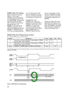