PIC18F2480/2580/4480/4580
26.1.1
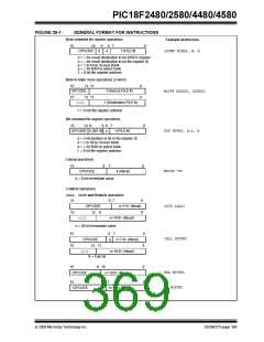
STANDARD INSTRUCTION SET
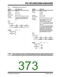
ADD Literal to W
ADDLW
ADDWF
ADD W to f
Syntax:
ADDLW
k
Syntax:
ADDWF
f {,d {,a}}
Operands:
Operation:
Status Affected:
Encoding:
Description:
0 ≤ k ≤ 255
Operands:
0 ≤ f ≤ 255
d ∈ [0,1]
a ∈ [0,1]
(W) + k → W
N, OV, C, DC, Z
Operation:
(W) + (f) → dest
0000
1111
kkkk
kkkk
Status Affected:
Encoding:
N, OV, C, DC, Z
The contents of W are added to the
8-bit literal ‘k’ and the result is placed
in W.
0010
01da
ffff
ffff
Description:
Add W to register ‘f’. If ‘d’ is ‘0’, the
result is stored in W. If ‘d’ is ‘1’, the
result is stored back in register ‘f’.
Words:
Cycles:
1
1
If ‘a’ is ‘0’, the Access Bank is selected.
If ‘a’ is ‘1’, the BSR is used to select the
GPR bank.
Q Cycle Activity:
Q1
Q2
Q3
Q4
If ‘a’ is ‘0’ and the extended instruction
set is enabled, this instruction operates
in Indexed Literal Offset Addressing
mode whenever f ≤ 95 (5Fh). See
Section 26.2.3 “Byte-Oriented and
Bit-Oriented Instructions in Indexed
Literal Offset Mode” for details.
Decode
Read
literal ‘k’
Process
Data
Write to W
Example:
ADDLW
15h
Before Instruction
10h
After Instruction
25h
W
=
Words:
Cycles:
1
1
W
=
Q Cycle Activity:
Q1
Q2
Q3
Q4
Decode
Read
register ‘f’
Process
Data
Write to
destination
Example:
ADDWF
REG, 0, 0
Before Instruction
W
REG
=
=
17h
0C2h
After Instruction
W
REG
=
=
0D9h
0C2h
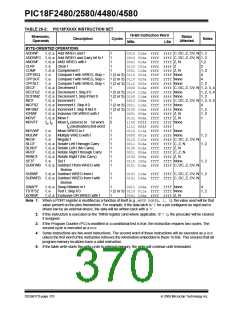
Note:
All PIC18 instructions may take an optional label argument preceding the instruction mnemonic for use in
symbolic addressing. If a label is used, the instruction format then becomes: {label} instruction argument(s).
© 2009 Microchip Technology Inc.
DS39637D-page 373

 MICROCHIP [ MICROCHIP ]