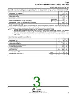
TL594
PULSE-WIDTH-MODULATION CONTROL CIRCUITS
SLVS052C – APRIL 1988 – REVISED JULY 1999
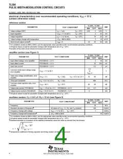
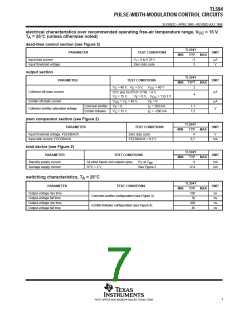
electrical characteristics over recommended operating free-air temperature range, V
A
= 15 V,
CC
T = 25°C (unless otherwise noted)
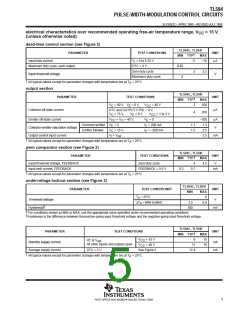
dead-time control section (see Figure 2)
TL594Y
TYP
–2
PARAMETER
TEST CONDITIONS
UNIT
MIN
MAX
Input bias current
V = 0 to 5.25 V
I
µA
Input threshold voltage
Zero duty cycle
3
V
output section
TL594Y
PARAMETER
TEST CONDITIONS
UNIT
†
MIN TYP
MAX
V
C
= 40 V,
V
= 0 V,
V
CC
= 40 V
2
E
Collector off-state current
Emitter off-state current
µA
DTC and OUTPUT CTRL = 0 V,
4
V
V
V
V
= 15 V,
V
= 0 V,
V
E
= 1 to 3 V
C
E
CC
= 0
= V = 40 V,
C
V
µA
CC
Common emitter
Emitter follower
= 0,
I
I
= 200 mA
1.1
1.5
E
C
C
E
Collector-emitter saturation voltage
V
= 15 V,
= –200 mA
pwm comparator section (see Figure 2)
TL594Y
TYP
4
PARAMETER
TEST CONDITIONS
UNIT
MIN
MIN
MAX
MAX
Input threshold voltage, FEEDBACK
Input sink current, FEEDBACK
Zero duty cycle
FEEDBACK = 0.5 V
V
0.7
mA
total device (see Figure 2)
TL594Y
TYP
9
PARAMETER
TEST CONDITIONS
UNIT
Standby supply current
Average supply current
All other inputs and outputs open,
DTC = 2 V,
R
T
at V
ref
mA
mA
See Figure 2
12.4
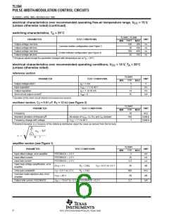
switching characteristics, T = 25°C
A
TL594Y
TYP
100
PARAMETER
TEST CONDITIONS
UNIT
MIN
MAX
Output-voltage rise time
ns
ns
ns
ns
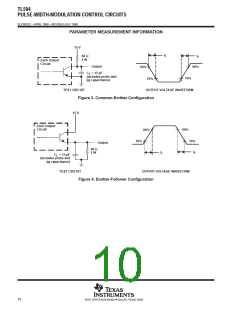
Common-emitter configuration (see Figure 3)
Emitter-follower configuration (see Figure 4)
Output-voltage fall time
Output-voltage rise time
Output-voltage fall time
30
200
45
7
POST OFFICE BOX 655303 • DALLAS, TEXAS 75265

 TI [ TEXAS INSTRUMENTS ]