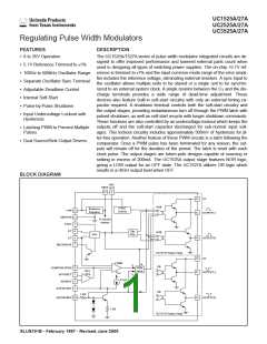
UC1525A/27A
UC2525A/27A
UC3525A/27A
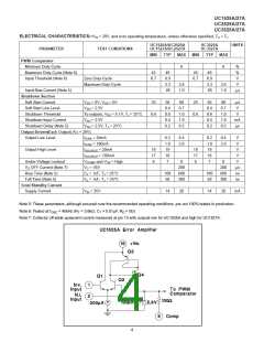
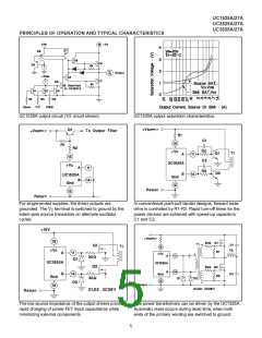
UC1525A oscillator schematic.
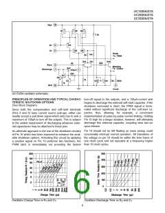
PRINCIPLES OF OPERATION AND TYPICAL CHARAC- turn-off signal to the outputs; and a 150µA-current sink
TERISTIC SHUTDOWN OPTIONS
(See Block Diagram)
begins to discharge the external soft-start capacitor. If the
shutdown command is short, the PWM signal is termi-
nated without significant discharge of the soft-start ca-
Since both the compensation and soft-start terminals
(Pins 9 and 8) have current source pull-ups, either can
readily accept a pull-down signal which only has to sink a
maximum of 100µA to turn off the outputs. This is subject
to the added requirement of discharging whatever exter-
nal capacitance may be attached to these pins.
pacitor, thus, allowing, for example,
a convenient
implementation of pulse-by-pulse current limiting. Holding
Pin 10 high for a longer duration, however, will ultimately
discharge this external capacitor, recycling slow turn-on
upon release.
Pin 10 should not be left floating as noise pickup could
conceivably interrupt normal operation. All transitions of
the voltage on pin 10 should be within the time frame of
one clock cycle and not repeated at a frequency higher
than 10 clock cycles.
An alternate approach is the use of the shutdown circuitry
of Pin 10 which has been improved to enhance the avail-
able shutdown options. Activating this circuit by applying
a positive signal on Pin 10 performs two functions; the
PWM latch is immediately set providing the fastest
Oscillator Charge Time vs RT and CT.
Oscillator Discharge Time vs RD and CT.
6

 TI [ TEXAS INSTRUMENTS ]