NCH-RSL10-101WC51-ABG超低功耗无线连接器!
日期:2022-5-18NCH-RSL10-101WC51-ABG可以发货3200只,如需要更多请联系15818661396

NCH-RSL10-101WC51-ABG优势和特点:
接收灵敏度(蓝牙低功耗技术模式,1Mbps):?94dBm
数据速率:62.5kbps 至 2000kbps
发射功率:?17dBm 至 +6dBm
峰值接收电流:5.6mA (1.25V VBAT)
峰值接收电流:3.0mA (3V VBAT)
峰值发射电流 (0.0dBm):8.9mA (1.25V VBAT)
峰值发射电流 (0.0dBm):4.6mA (3V VBAT)
通过 Bluetooth 5 认证,支持 2Mbps
ARM Cortex-M3 处理器时钟频率高达 48MHz
用于音频编解码器的 LPDSP32
电源电压范围:1.1V 至 3.6V
电流消耗 (1.25V VBAT):
深度休眠、IO 唤醒:50nA
深度休眠、8KB RAM 保持:300nA
音频流(7kHz 音频 BW):1.8mA 接收/发射
电流消耗 (3V VBAT):
深度休眠、IO 唤醒:25nA
深度休眠、8KB RAM 保持:100nA
音频流(7kHz 音频 BW):0.9mA 接收/发射
384kB 闪存
高度集成的片上系统 (SoC)
支持 FOTA(固件无线)更新
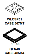
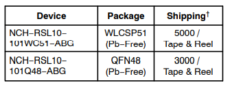
采用超小型WLCSP51和QFN48封装
NCH-RSL10-101WC51-ABG应用:
健身追踪器和活动监视器
智能手表
助听器和听力设备
心率监视器
血糖监测仪
连续血糖监测仪
脉搏血氧仪
物联网应用
智能锁
照明应用
更多参数:
| 产品属性 | 属性值 | |
|---|---|---|
| 制造商: | onsemi | |
| 产品种类: | RF片上系统 - SoC | |
| RoHS: | 详细信息 | |
| 类型: | Bluetooth | |
| 核心: | ARM Cortex M3 | |
| 工作频率: | 2.4 GHz | |
| 最大数据速率: | 2 Mbps | |
| 输出功率: | 6 dBm | |
| 灵敏度: | - 94 dBm | |
| 工作电源电压: | 1.1 V to 3.3 V | |
| 接收供电电流: | 5.6 mA | |
| 传输供电电流: | 8.9 mA | |
| 程序存储器大小: | 384 kB | |
| 封装 / 箱体: | WLCSP-51 | |
| 封装: | Reel | |
| 封装: | Cut Tape | |
| 封装: | MouseReel | |
| 商标: | onsemi | |
| 数据总线宽度: | 32 bit | |
| 数据 RAM 大小: | 76 kB, 88 kB | |
| 数据 Ram 类型: | SRAM | |
| 高度: | 0.35 mm | |
| 接口类型: | GPIO, I2C, PCM, SPI, UART | |
| 长度: | 2.325 mm | |
| 最大时钟频率: | 48 MHz | |
| 最大工作温度: | + 85 C | |
| 最小工作温度: | - 40 C | |
| 安装风格: | SMD/SMT | |
| 产品类型: | RF System on a Chip - SoC | |
| 程序存储器类型: | Flash | |
| 系列: | RSL10 | |
| 工厂包装数量: | 5000 | |
| 子类别: | Wireless & RF Integrated Circuits | |
| 技术: | Si | |
| 宽度: | 2.364 mm | |
| 单位重量: | 1 g |

PCB Design Guidelines 1. Decoupling capacitors should be placed as close to the related balls as possible. 2. Differential output signals should be routed as symmetrically as possible. 3. Analog input signals should be shielded as well as possible. 4. Pay close attention to the parasitic coupling capacitors. 5. Special care should be made for PCB design in order to obtain good RF performance. 6. Multi?layer PCB should be used with a keep?out area on the inner layers directly below the antenna matching circuitry in order to reduce the stray capacitances that influence RF performance. 7. All the supply voltages should be decoupled as close as possible to their respective pin with high performance RF capacitors. These supplies should be routed separately from each other and if possible on different layers with short lines on the PCB from the chip’s pin to the supply source. 8. Digital signals shouldn’t be routed close to the crystal or the power supply lines. 9. Proper DC?DC component placement and layout is critical to RX sensitivity performance in DC
