X40430/X40431 – Preliminary Information
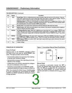
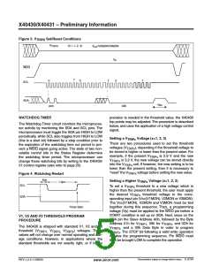
Figure 3. V
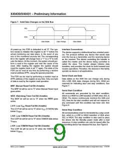
Set/Reset Conditions
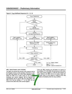
TRIPX
V
(X = 1, 2, 3)
TRIPX
V
/V2MON/V3MON
CC
V
P
0
WDO
SCL
7
0
0
7
7
SDA
t
WC
A0h
00h
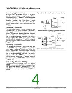
WATCHDOG TIMER
precision is needed in the threshold value, the X40430
trip points may be adjusted. The procedure is described
below, and uses the application of a high voltage control
signal.
The Watchdog Timer circuit monitors the microproces-
sor activity by monitoring the SDA and SCL pins. The
microprocessor must toggle the SDA pin HIGH to LOW
periodically, while SCL also toggles from HIGH to LOW
(this is a start bit) followed by a stop condition prior to
the expiration of the watchdog time out period to pre-
vent a WDO signal going active. The state of two non-
volatile control bits in the Status Register determine
the watchdog timer period. The microprocessor can
change these watchdog bits by writing to the X40430/
31 control register (also refer to page 20).
Setting a V
Voltage (x=1, 2, 3)
TRIPx
There are two procedures used to set the threshold
voltages (V ), depending if the threshold voltage to
TRIPx
be stored is higher or lower than the present value. For
example, if the present V is 2.9 V and the new
TRIPx
V
is 3.2 V, the new voltage can be stored directly
TRIPx
into the V
cell. If however, the new setting is to be
TRIPx
lower than the present setting, then it is necessary to
“reset” the V voltage before setting the new value.
TRIPx
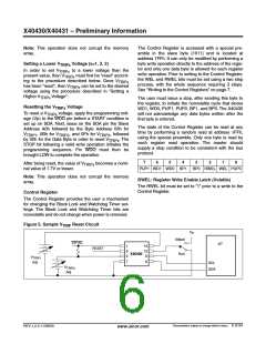
Figure 4. Watchdog Restart
.6µs
Setting a Higher V
Voltage (x=1, 2, 3)
1.3µs
TRIPx
SCL
To set a V
threshold to a new voltage which is
TRIPx
higher than the present threshold, the user must apply
the desired V threshold voltage to the corre-
TRIPx
SDA
sponding input pin (Vcc(V1MON), V2MON or V3MON).
The Vcc(V1MON), V2MON and V3MON must be tied
together during this sequence. Then, a programming
voltage (Vp) must be applied to the WDO pin before a
START condition is set up on SDA. Next, issue on the
SDA pin the Slave Address A0h, followed by the Byte
Timer Start
V1, V2 AND V3 THRESHOLD PROGRAM
PROCEDURE
Address 01h for V
, 09h for V
, and 0Dh for
TRIP1
TRIP2
The X40430 is shipped with standard V1, V2 and V3
V
V
, and a 00h Data Byte in order to program
. The STOP bit following a valid write operation
TRIP3
TRIPx
threshold (V
V
V
) voltages. These
TRIP1, TRIP2, TRIP3
values will not change over normal operating and stor-
age conditions. However, in applications where the
standard thresholds are not exactly right, or if higher
initiates the programming sequence. Pin WDO must
then be brought LOW to complete the operation
Characteristics subject to change without notice. 5 of 24
REV 1.2.3 11/28/00
www.xicor.com

 XICOR [ XICOR INC. ]